|
|
||
|
|
|
|
|
|
||
Truck Improvements for RV Use
|
|
|
|||||||||||||||||||||||||||||||||||||||||||||||||||||||||||||||||||||||||||||||||||||||||||||||||||||||||||||||||||||||||||||||||||||||||||||
|
|
Copyright © 2002-2017 John Mayer. All rights reserved. For reuse policy see Reuse Policy In this Section: (note: press the Home key to return to the Section Contents)
PressurePro Tire Monitor System We have been using a tire monitoring system since shortly after we started fulltiming in 2000. It has saved us from problems on numerous occasions by allowing us to catch tire inflation problems before they resulted in a blowout. It has been argued that if you check your tires every morning you don't need a monitoring system. I used to believe this too, until I picked up "road hazards" between checks (I check tires every time I stop) which caused catastrophic tire failure due to heat buildup from low pressure. Believe me, unless you are very lucky, just the damage repair savings from one bad blowout will more than pay for a tire monitoring system. Also consider, if you have a motorhome, that you will likely not know if you have a blowout on the toad. Even with the camera on it is likely that the first indication of a problem will be when the rim and tire overheats and starts smoking. The peace of mind provided by the monitor is worth it to me. Until the summer of 2004 we used a SmarTire system, which we really
liked. The SmarTire system we had monitored up to 6 tire positions, and
wirelessly transmits temperature and pressure for each position. It
worked well, but its weakness is the number of positions it will
support. We needed to monitor the tractor, as well as 6 positions on the
trailer. This prompted us to look for a system that would support more
than 6 tires. Another thing I disliked about SmarTire was it's inability
to report over 127psi (this may have been corrected on later versions).
On high pressure trailer tires (110psi) you can easily exceed the 127
psi limit in hot weather. [Note: As of 2005 SmarTire has a monitor
system available that supports the number of wheel positions we would
require. ] There are two basic types of tire monitor systems available: those that attach to the valve stem (like PressurePro), and those that place sensors inside the tire (like SmarTire). There are pros and cons to both types of systems. The largest negative to the internal systems is the difficulty and expense of installation. SmarTire, although difficult to install, does report internal tire temperatures as well as pressure. If you think you would like this feature, they are worth checking out. There are a number a systems on the market that support 12 or more tire positions, and use the valve stem sensor to transmit pressure information. However, until PressurePro was developed there were significant issues with each of the systems; in my mind, at least. Some systems require relays on the trailer and truck, since they will only transmit a short distance. Even SmarTire required that we install an auxiliary pickup antenna on the rear of the truck, due to the overall length. Some systems require transmitters to be custom built for a specific tire pressure. This means you can't move the sensor from the trailer to the truck. This also means you can't decide to upgrade tires on the trailer from (say) E rated tires (at 80psi) to G rated tires at 110 psi. Or even to change the inflation pressure based on loading. PressurePro has the following desirable characteristics:
Negatives:
Balancing all the pros/cons, I think that PressurePro is still the best valve stem
system available (as of 2009). You can find additional info at the
Pressure Pro website. For a comparison of the features of the various brands of monitors available (as of November 2006) you can download the Excel file Tire Monitor Comparison. Although this is now somewhat dated, the comparison will give you things to think about as you evaluate the available brands. A final note on the PressurePro system: there are other valve stem tire monitors on the market that sell for less. One thing to consider in evaluating those against PressurePro is the history of the company, and service after the sale. New products always have quirks associated with them. Working out these issues takes time. PressurePro has gone through all this already, has the reputation for providing outstanding service, and they have been in business for quite a while. If needed, they will get you a new sensor very quickly, and will work with you directly if you have issues. I can tell you from personal experience that a simple phone call had a new sensor to me within 2 days when I had a sensor damaged from a road hazard. And there was no charge - although I would not count on not being charged. Sometimes the cheapest system is not the best way to go. This technology is maturing and there are products other than PressurePro that work well. Just be sure that you have a source of service for the product you buy.
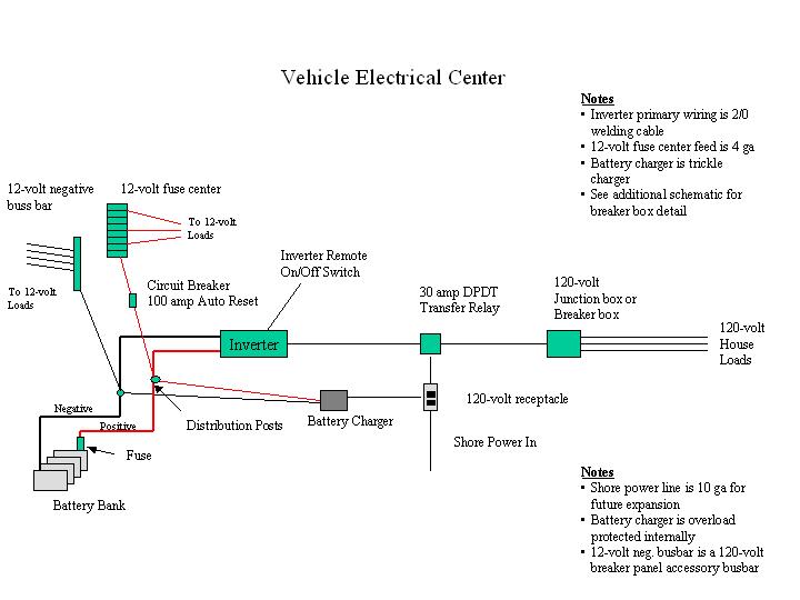
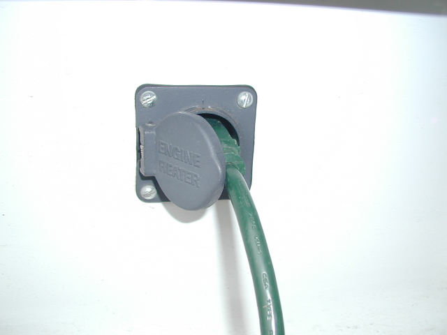
The purpose of the wiring center is to supply 12 /120-volt power for
the cab, and to the trailer plug for the 5th wheel. This article covers
the basic how to's along with resources for parts and accessories. The
wiring practices described here are commonly used and are code
conforming to the best of my knowledge, but this document should not be
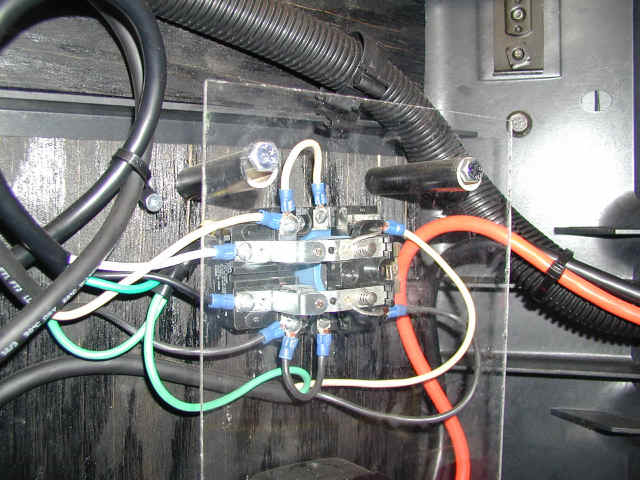
taken as electrical advice - it is simply the way I did it. My wiring center is in the driver's side compartment, on the forward
(left) wall. It is built on top of ¾ plywood, which was glued to the
plastic walls of the compartment with construction adhesive. Use of the
plywood simplifies installation of components and permits use of cheap,
commonly available fasteners without penetration of the compartment
walls. I painted the wood black before installation - this provides a
more pleasing appearance. To protect the terminals and wires from shorts
and damage, two plexiglass panels cover the appropriate areas of the
walls. This prevents cargo in the storage box from impacting the wire
center. The plexiglass is mounted with ¼ x 3.5 lag bolts through ½
plastic pipe used as standoffs. The area over the inverter is not
covered to ensure proper heat dissipation. The wire center is shown in
the picture above without the plexiglass panels in place. The
perspective is looking forward from the rear of the truck. All wiring is fed into the compartment from a 3" x 1" hole in the floor. The easiest way to do this is with a 1" drill bit - drill a hole at each end of the cutout, and use a Dremel tool with a cutting blade to connect the holes. The hole is a little crowded - you may want to consider a slightly larger hole.
A far better alternative to the Hoppy is now available. Shown to the
left, the ET Jackalopee is a custom tailight converter available from
Szmyt ET
Hitches and Custom Design. It provides for full isolation of
the tractor from the trailer, and is capable of handling up to 60 amps
per line. It is a far superior solution to any other available on the
market, and is now the only one I would use. The instructions that come
with the Jackalopee are very complete, and explain the entire trailer
lighting control system better than any previous documentation I have
seen. In my wiring, the inputs to the converter come from the existing green Volvo trailer feed wire, which was originally terminated behind the cab. This was disconnected and moved into the storage box, through the hole in the floor. Turn signals and brake light feed were picked up from the original trailer connector. The brake light signal was fed forward (with a 14-gauge wire) into the cab to act as the brake signal for the brake controller. It was easier to pick the brake signal up here than to find the brake signal in the cluster of wires in the Volvo fuse center, and since you have to run a wire back from the controller anyway, it was no additional work. The braking output from the brake controller is returned to the drivers compartment on a 10-gauge wire to the wire center, where it is soldered to the new trailer connector line, which then runs to the rear of the truck. This brake line feeds 12v power to the trailer braking system and needs to be at least 10 gauge to minimize voltage drop. Any connection in this line needs to be soldered, or you will loose too much voltage. One additional note on the trailer lights: You might want to consider
fusing the turn/running light output lines from the light
converter. This will protect the converter from shorts in
the trailer. Otherwise, you might damage the converter when you
have a short in the trailer. It is cheap insurance, since no matter what
converter you use you will have more than a few dollars tied up in it.
And you do not want to have an issue with a destroyed converter on the
road. There are two ways to proceed on the brake controller, depending on what type of brakes the trailer has: standard electric drums, or hydraulic disc brakes. Typically, both types of brakes are actuated with an electric signal from the truck - both the truck and the trailer use an electrical signal to run the brakes. The reason for this is so any truck can pull any trailer (in theory). With conventional drum brakes the electrical signal is sent back to the trailer by the brake controller, and actuates the magnets on the drums directly. This leads to lots of issues; primarily, bad connections in the electrical connectors that drops the voltage too low causing a lack of current at the brakes. Wires that are too small will do this too; you need 10 gauge wires all the way to the brakes. The end result of a pure electrical system is often marginal braking on the trailer because the magnets are not running at optimal power. With disc brakes, the trailer has hydraulic brake actuation, since electrical means of directly clamping the pads would be ineffective. The electrical signal from a conventional brake controller in the truck is sent back to the trailer, and then converted to hydraulic pressure via the electric/hydraulic actuator which interfaces to a master cylinder just like on a car. This works as well as the electrical signal feeding the actuator, so your braking effectiveness is somewhat dependent on the quality of the controller used in the truck. Some electric/hydraulic brake systems require specific controllers to interface with their actuators. You need to check with your trailer brake manufacturer to ensure your controller of choice will work well with your hydraulic trailer brakes. The issue with all electrically-based controllers is that they do not predict the braking force requested by your foot on the pedal well - a LOT is lost in that "translation". A superior method of translating the braking request to the brake actuator is to directly tap into the air brake system of the tractor. This is the only method of getting true proportional braking. All "pure electric" methods only simulate proportionality via pendulums or gyroscopes, although the gyroscopic method is quite good. I originally used a Prodigy controller, which worked OK. A Prodigy is an advanced pure electric controller that uses pendulum technology. It is probably the best of the pendulum controllers. A few years later I moved to the Hensley TruControl Gold, which works as well as can be expected of a controller that is not integrated into the truck braking system. The Hensley uses gyroscopic technology to sense deceleration of the vehicle. It is far superior to the Prodigy and other pendulum controllers. If I was to do this over again and wanted to maintain an electrical braking signal from the truck to the trailer, I would use an air-over-electric proportional controller; the Hayes-Lemmerz (#100400-B ). Most of the wiring would be the same except for picking up the brake line signal. The major difference is that these controllers tap a brake air line to give you true proportional braking with the air brake system of the truck, instead of using the electrical brake signal. The Hayes uses a mechanical servo tapped into the air line that directly
detects the amount of brake application.
I now use a BluDot brake actuator in the trailer. It does not require a brake controller, since it operates directly off the truck air system via the gladhands on the truck, just like a semi-trailer connection. From an operational and function perspective this is the best system available - the truck and trailer operate as a SINGLE unit. Like anything else, there are pros and cons to using a BluDot. You can find an article on my BluDot installation in the RV Improvements section.
All of my wires run from the storage box, down through the floor, and then forward under the cab. They are strapped to the existing wire bundle that is attached to the frame. They re-enter the cab just forward of the drivers seat, just inward of the removable floor trim plate through several small holes drilled in the cab floor. They proceed forward to the front of the truck under the floor mat, and from there either up to the top of the dash, or through the dash, as appropriate to their function. Some wires run along the top of the dash down by the defroster outlets in black split loom. You don't see them in that position. These wires are the camera wires for my backup cameras, and the telephone cable that controls the remote On/Off for the inverter. The brake signal (input) and return (output) wire from the brake controller are run inside the dash to the controller which sits just to the right of the drivers right knee. A note about penetrating the
floor: this is fine in the metal floor of a Volvo, but if you have a Kenworth or Peterbuilt make sure you do not have the balsa wood cellular
floor - this can not have holes cut in it without reinforcing them
properly. Use the holes the manufacturer
supplied. You could also run the wires forward into the engine compartment and
bring them through the firewall through a grommet. I found it easier to
bring them in at the door jamb. The 120 volt AC line that feeds the receptacle on the dash runs on
the opposite side of the truck routed under the mat in a similar
fashion, except that it comes through the rear of the storage
compartment, behind the refrigerator (which sits behind the passenger
seat), and then under the floor mat. I ran the 120-volt power on the
opposite side of the truck so that its proximity to the camera line
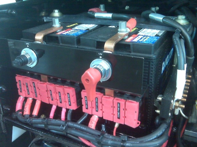
would not cause interference. The wire center is supplied with 12-volt power directly by the
inverter cables. The inverter cables terminate in distribution hubs at
the wire center, which allows you to easily tap power for various
functions. All negative wires terminate directly onto the negative
distribution hub. There are no terminations to the chassis - this will
prevent bad grounds in the future.
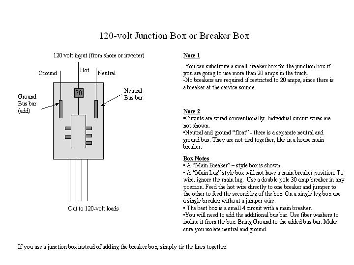
You can add a negative 12-volt buss bar if you need one (you won't
need it if you spend the few $ for the Blue Sea panel shown). Use a buss
bar from an AC load center. These are available in the electrical
section of Home Depot or Lowes, and are used to add neutral and ground
busses to load centers. Just screw it to the plywood and you are ready
for hookups. Use a neutral lug and 4 or 6 ga cable to tie it to the
distribution hub. You could buy a negative buss bar from a specialty
catalog - these have the advantage of having a post to tie in the
negative feed line. They also cost upward of $99, depending on what you
get. Future expansion of the system is much easier with the fuse center in
place (I have learned this the hard way). In the cab, the brake controller is supplied with 12-volt power from
the distribution hub on the firewall, directly above the steering
adjustment pedal. Ground is tapped directly off the
battery, following the installation instructions. Alternatively, you
could tap the negative post behind the steering adjustment pedal, but
the controller instructions are specific about
tapping the battery directly. Both the ground and the positive are 10
gauge wire - overkill, but I had it.
In my installation the new trailer wire harness is supplied with 12-volt power
for the trailer battery bank (position 4 in the diagram) from the
distribution hub in the storage compartment. Typically, you would tap
the output of the alternator to supply the trailer line. You would use a
battery isolator or a solenoid to separate the banks - really only
required if you keep the trailer and truck plugged together for long
periods. If you really want to get fancy you could use a "smart"
charging switch, or a cross-charge regulator in place of an isolator or
solenoid. This would ensure that both the truck and trailer battery
banks get a full charge off the alternator. If you don't use a "smart"
charging switch then the alternator will shut down when the first
battery bank reaches the cut-off voltage of your truck regulator. This
will leave the other bank (typically the trailer bank) without a full
charge. NEVER use a battery A/B/Both switch. These just cause problems
and if not used correctly can cause a system-wide electrical surge (if
you switch it wrong while the alternator is running) that will burn out
your alternator diodes and/or other truck electrical components. In my application these are all unnecessary. Since I have a large
solar system (480 watts, 29 amps), I find that satisfactory for my
trailer battery bank charge. I only want access to 12-volt power at my
trailer plug in order to run 12-volt appliances (like a 12-volt water
pump for pumping water from the truck to my trailer when boondocking).
You will probably want to tap your alternator output if you depend on
the tractor to charge your trailer battery bank. Using the tractor
battery bank as the charge source for the trailer bank will result in
the trailer bank never being fully charged. On the dash behind the CB radio holder I added a three outlet 12-volt
accessory receptacle. This is handy for the GPS, etc. This is
permanently tapped off of the CB power point, from behind. A side note on the Volvo electrical monitor: Many Volvo's have an electrical monitoring system designed to cut off power to various electrical items when battery voltage falls below a designated threshold. An alarm goes along with this. On my Volvo, along with many others, this alarm would go off even when voltage was "normal". In doing the work above, I discovered that the alarm was grounded to the rear of the power center. Removing the ground wire stopped the alarm and does not seem to have any side effects. You may, or may not, have the same wiring set-up.
I chose to go the lower-cost route. Mainly because I do not envision
using my truck as an RV for long periods of time without shore power
hookups. So my 120-volt inverter needs directed me to the lower cost
inverter. This drove the rest of the electrical design. I will describe
the details of my implementation, but I have also included a schematic
and details of the more sophisticated implementation. Mark Bruss chose
to use a high-powered inverter with his Volvo 770. You can see the
details of his electrical center at
Mark Bruss' website. The inverter I used is a Xantrex XPower 1200 (1000 watts, continuous)
with the optional remote control. I purchased this online, through
http://www.buy.com. At the time, they
had the best price (around $170 for both). I chose the 1200 because the
highest power appliance I intend to power is a 600-watt microwave, and
this inverter has adequate power to do it. There is also an XPower 1750
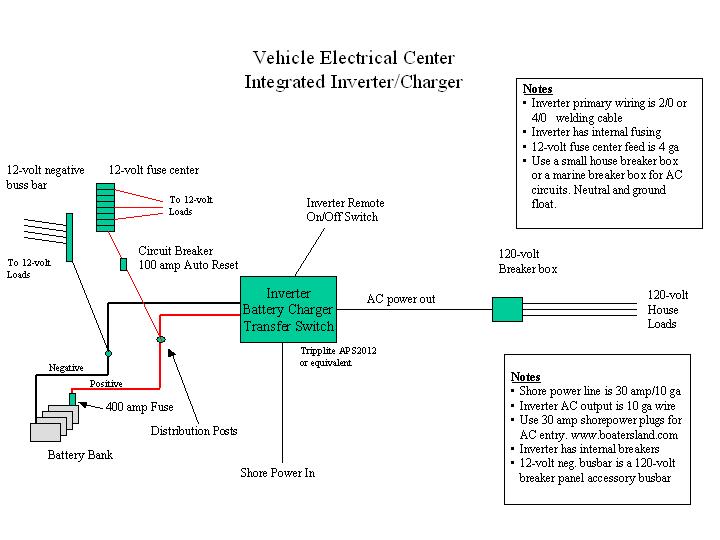
(1500 watts, continuous) available; it uses the same remote control. If you want an integrated inverter/charger/transfer switch then the
Tripplite APS2012 would be a good choice. They run around $600 online;
you will also want the $105 remote switch. (Prices are approximate at
the time of this writing.) The integrated
inverter/charger/auto switch costs more, but makes the wiring a little
simpler. Ideally, any inverter you choose should be direct wire (for both AC
and DC) and should have a remote on/off switch. Direct wire for the AC
output circuit simplifies the wiring to your house loads. If your
inverter has outlets, most likely all of the rated output is available
from any of the outlets. Just use a 12 ga extension cord (cut to the
appropriate length, or a direct-wire plug) to supply the 120-volt power
to either your 120-volt junction box, or loadcenter. The remote on my inverter (and most of them) uses a 4-wire telephone
cable. It attaches to the back of the inverter. The control panel on
mine happens to be the same height and brushed aluminum finish as the
Eaton Autoshift display, so I removed a screw from the Eaton panel and
mounted the remote right on it. If you don't know differently, it almost
seems like it belongs there. A note on inverter technology. All the inverters above are modified
sine wave. You may hear that using anything but a pure sine wave
inverter will cause interference problems with TV's or that certain
devices won't run at all. While this is certainly possible, depending on
the device, modern modified sine wave inverters run almost all devices
"cleanly". I would not hesitate to use a modified sine wave inverter for
everything except very specialized applications. Some TV's will not work
with modified sine wave - but I have never seen one, and I have
installed many inverters in both RV's and vehicles. Oxygen concentration
equipment, laser printers and certain battery chargers all need pure
sine wave. Almost all other devices work fine on modified sine wave.
Microwave ovens will run at reduced output on all inverters, so you simply program more time into them. We find it is best to run microwaves on "high" only. Microwaves of all varieties are sensitive to the DC input voltage. Less DC voltage, less cooking. This is true even though the AC output voltage of the inverter is held fairly constant. Don't plan on cooking extensive meals with your microwave - it is best used for re-heating only. My inverter is mounted upside down for access to the lugs. To the
right of the inverter is a 30 amp DPDT relay with a 120-volt coil. Any
good electric supply house should have them. The relay takes as input
the 120-volt inverter output and the shore power line. The shore power
also feeds the coil, so when shore power is available it will always be
favored. A cover is available for the relay, and I recommend spending
the extra $20 to get it. I covered the entire area with a plexiglass
panel so the power lugs are protected, but the relay cover would
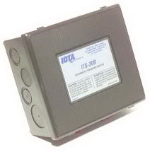
probably be better. The relay cost $27 without the cover. An alternative to "building your own" transfer switch from a relay is
to simply buy a transfer switch. Iota makes a good one at a reasonable
price. A 30 amp version is $55 at
http://www.solarseller.com. If you are going to buy the cover for
the DPDT relay like I used, just buy the transfer switch instead; you
will be better off. Of course, if you are using the higher-priced inverter/charger with
an auto switch capability you will not need to set up your own transfer
switch - it is built into the inverter. In my installation the output from the transfer relay goes to a 4
inch electrical junction box where it is split into 2 lines. The first
goes to feed the refrigerator and microwave. It is routed through the
back of the storage compartment, wire wrapped to the existing wire
bundle. Instead of mounting a receptacle in/on the passenger-side
storage compartment, I used a direct-wire multistrip, which I mounted
above the blower inside the passenger-side storage compartment. The
plugs for the refrigerator and microwave enter this compartment through
a hole behind the refrigerator. This was easier and just as effective as
a wall-mounted receptacle. I specifically did not want a receptacle
because I wanted the refrigerator to be flush against the side of the
storage compartment - with a receptacle the plug would have interfered
with flush mounting. I also did not want to see any cords in the cab
area.
A note about the refrigerator. I decided not to use a 12-volt
fridge. Mainly because of the cost - over $500. I found a small
Whirlpool 120-volt energy efficient refrigerator for
$58 at Lowes that only draws 1.1 amps AC. The battery bank can easily
sustain the 12 amp DC load this fridge places on it (remember, you loose
power during conversion). I don't run it that much when not on shore
power, or driving. The additional advantage of this refrigerator is that
its width permits it to fit between the seat belt mount and the bed, and
its height permits the passenger seat to recline some. After living with
this refrigerator for over seven years I am still very pleased with it.
It cools down extremely fast, and I can leave it on for days at a time
on the inverter with no apparent effect on the battery bank. When
looking for a refrigerator there are two important characteristics: the
amp draw, and the width. Look for a fridge that is 18" or less, or you
will have trouble fitting it behind the passenger seat in a Volvo
610/630. Ground the inverter following the manufacturer's instructions. If you
are using an inverter with a transfer switch, the AC ground input and
output lines have lugs or ground wires inside the inverter to attach to.
If you are using a small inverter and its inbuilt receptacle then the AC
output line ground is simply part of the wire you plug in. Internal to
the inverter, it is likely bonded to the chassis. Almost all larger inverters have a separate external chassis ground
lug on them. This goes directly to chassis ground - NOT to the DC
negative buss bar, or the battery ground, or the AC load center. Usually,
6 AWG wire is sufficient, but the inverter manufacturer will specify the
wire size depending on the inverter size. The AC output from the inverter goes to some sort of AC distribution
panel (or junction box, if not protected by breakers). In the case of
smaller inverters without an inbuilt transfer switch you will run it
through an external transfer switch or relay to control shore power
selection. If you are using an external transfer relay like the Iota, follow
their instructions on grounding hookup. There will either be bonding
terminals inside the transfer switch, or they will specify the method
that the grounds be bonded to each other. If you are using a DPDT relay, like I did, then bond all the grounds together. If you use a wire nut, make sure you tape it. You can see this in the picture of the DPDT relay (follow the green wires). Establish a chassis ground either where you merge the grounds (add an extra chassis ground wire to the three existing ground wires) , or at the AC distribution panel or box, depending on how you prefer to wire. When not connected to AC shore power the chassis ground will offer some protection, but it is nowhere near as good as an earth ground. When on shore power, ground will flow back to the utility ground. Adding a
Separate House Battery Bank to the Truck
Adding a separate house bank solves the problem of overburdening your starting bank, but creates its own set of issues – mainly cost and complexity. A lot of cost, and a lot of complexity. In order to have a properly functioning house bank you need to have a charging source for it. Deep cycle batteries are more sophisticated than starting batteries and require a multi-stage charger in order not to “kill” them over time. Using just your alternator with its stock regulator will result in a constant undercharge – remember, that alternator/regulator is designed to maintain starting batteries, which are rarely discharged more than 5%, and have a different charge curve than deep cycle batteries. Fortunately, if you are implementing a house bank you are probably already using an inverter/charger which is designed to manage deep cycle batteries. So you will have a way of fully charging your house bank when hooked to shore power. Adding a separate battery bank for your "house" loads means you have
to:
You need to decide where to put the batteries. Use your imagination, but remember, it is best to keep the wire run to the inverter as short as possible. Definitely not farther than 10’, max, which includes twists and turns to get there. If you have more than 5’ of run, use 4/0 cable, despite what you might read in your inverter manual. Actually, I always use 4/0 for any inverter over 1700 watts. You also need to make sure the inverter is not in the same enclosure as the battery bank. Batteries are explosive devices – inverters have relays and other electrical components in them. Batteries also outgas while charging. You don’t want your inverter in the hostile environment of a battery. Also, when locating the battery box, make sure it is easy to service the battery bank. You will need to check fluid level at least once a month, especially if the house bank is heavily used.
We already know that we need a 3-stage charger to properly maintain
the house bank. Fortunately the inverter has such a beast, so you have a
good charge source when plugged in. What about while driving? An automotive alternator, along with its regulator, is designed to
charge a starting battery bank. When you add the house bank there is no
method to add a separate charging circuit to the existing regulator to
independently charge the house bank. It is simply not designed for that.
In addition, you don’t want your house loads to draw down your starting
battery. That requires that the house and starting bank be isolated from
one another when you are using power, but that they be combined when the
alternator is supplying power for recharging. The one thing you never want to use to combine banks is a cheap
A/B/ALL battery switch. You WILL forget to properly switch it, and if
done improperly it will destroy your alternator, and probably much of
the computer electronics in your vehicle. Don’t use it unless it has
starting isolation to protect your circuits. You also need to make sure
it is rated for the expected loads. The simplest way to combine (and by combine, we are talking for
charging purposes, not for starting) the banks for charging is with a
simple high-power relay (at least a 150 amp normally open). When the engine is
running the relay is closed and charge output from the alternator goes
to both banks. When the engine is off, the relay opening isolates the
banks. Under $40, but you will never get a good charge on the house
bank. That is because the starting bank will probably come up to full
charge first, and the regulator will shut the charge down to both banks.
Remember, the regulator knows nothing about two banks. This might be OK
if you intend to plug into shore power often and use the high-power
charger in the inverter to maintain the house bank. An alternative, and a better solution, is to use a solenoid with a
charging controller integrated with it. There are various models on the
market. The logic in the controller maintains and manages the charge to
both banks, based on various settable conditions. It is acting as a
smart charge regulator. Some of these even have temperature
compensation. They are not cheap however. Expect in the $150+ range,
depending on features. Take a look at the Ample Power Auto switch. A
disadvantage to all types of relays/solenoids is that they can fail. In
some cases they can also push a high voltage surge through the system,
although this is rare. You could also use an isolator with a diode built into it. The typical reason not to use a diode-based isolator is that they consume about .5 to 1.5 volts while active. This lowers the voltage to the banks and results in never obtaining a full charge. If you use an isolator with a Schottky diode instead of a silicone diode you will eliminate most of this loss. At 100 amps, expect to loose around .45 volts with a schottky-based isolator, and around .8 volts with a silicone-based isolator. The isolator is a much better, but a relatively expensive, solution at around $140+ depending on features (they go up fast). Hellroaring makes an advanced isolator with minimal voltage drop. Check out the BIC-85150A for around $150. Again, if you know you are going to correct this charge deficit with shore power, a low cost isolator can be an adequate solution. A regular old cheap isolator rated at 150 amps should be around $70 or less. Blue Sea also makes an ML-Series automatic charging relay that will do a good job. It will charge either or both batteries and has a charge sense line for both. It can also safely combine the banks for starting purposes, and has no voltage drop on charging. Most important, it has battery bank isolation, so that during starting you do not put shock loads or surges into the house systems. This comes with a remote panel. Also look at the devices and monitors made by
National Luna. They make expedition equipment typically used to
monitor dual battery systems in Jeeps and other "expedition" vehicles. Another alternative, although I doubt most of us need it, is to
replace or augment the existing regulator with a dual output regulator
with inbuilt 3 stage charging. There are various capabilities and
alternatives here. You will get a great charge, but expect to pay $400+
by the time you set up your system properly. I recommend something like the Ample Power Autoswitch, The Blue Sea
relay, or the
Hellroaring isolator. It is a good compromise between cost and
functionality. It will give you a good charge, protect your batteries,
and is relatively simple to install. Without a way to determine battery state-of-charge you are risking
killing your batteries. You also don’t know how much energy is available
for your use. Any system using a separate house bank without a battery
monitor is an incomplete system, and typically is not going to be
satisfactory in anything but trivial use – in which case, you should
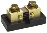
question why you have a separate house bank. There is only one critical measure, and that is ampere hours. An
amp-hour meter measures amps consumed and amps restored. It is like a
fuel gauge on your vehicle. All quality battery monitors have an
amp-hour function. They also measure voltage, and some have a simplified
“fuel gauge”-like display that gives a quick reading of battery charge
state (half full, ¾ etc.). You use the meter for various things –
finding the ampere consumption of an appliance while in use, determining
the amount of charge going back into the battery via the charger or
alternator, condition of the batteries (by how much charge they will
accept), and most importantly, how “full” your battery is. If you have
200 amps max to use, and you microwave something (say 4 amp hours) and
brew a pot of coffee (12 cups, say 33 amp hours), and watch an LCD TV
for an hour (about 8 amp hours), plus you have a phantom draw (more on
that later) of 8 amp hours (per day) you now know, through the meter,
that you have a deficit of 53 amp-hours. This is well within the 25%
rule (which would be 100 amp hours on a 400 amp hour battery bank). If
you did not have the battery monitor, you would never know. A note about phantom loads. Every system has consumption even if
nothing is “on”. This is called the phantom load. It comes from various
things like “instant on” TV’s, charging bricks, inverters left in
standby, microwave displays, and just electrical “leakage”. You need to
determine the phantom load on your system using the amp hour meter – the
phantom load adds up fast over a one or two day period.
Battery monitors also provide you with battery voltage, which is
really only useful to observe charge stage, or to determine if the
battery is really totally full or discharged. Voltage is not an accurate
measure of battery state of charge in between full and empty. The reason
is that voltage is only useful if the battery is at rest for 24 hrs
(i.e. no load for 24 hrs.) - not a practical option in a system being
used. There is a lot more to battery monitoring than I have described here.
Over time you will come to “know” your batteries, and how your system
operates normally. This will allow you to quickly pick up anomalies,
like marginal battery cells, before things become critical. Most of the
battery monitors come with pretty good tutorials. It can be pretty
overwhelming to try to learn everything at once. I would learn a little
at a time, watch your batteries, and you will be surprised how soon you
will understand them.
 In March 2004 we went to Kilgore, TX to have a custom body built
for our truck. We looked long and hard for the right body
builder - the right builder in our estimation is one who does
custom work, very high quality, is easy to work with, has
experience with our truck type, and is realistic in pricing. We
found all this and more in Herrin Welding Service, Kilgore TX.
Herrin Welding builds all kinds of custom truck bodies, from
simple to complex. They are a family owned business that can
build you anything you want - their bodies are built in steel,
which for a HDT is preferred, to add extra weight to the rear
suspension. You can email Herrin Welding at info@herrinhauler.com. Their phone number is 903-984-7139
and their web site is
www.herrinhauler.com. Those of
you who know me know that I am very fussy. You won't be
disappointed in Larry Herrin and his operation - give them a
try. To see some other examples of Herrin truck bodies you can
go to the
Other Herrin Truck Bodies page of
our old web site (I'll eventually move them). You can see
pictures of out truck bed on our
Picasa album. There are also pictures at the end of this
section. In March 2004 we went to Kilgore, TX to have a custom body built
for our truck. We looked long and hard for the right body
builder - the right builder in our estimation is one who does
custom work, very high quality, is easy to work with, has
experience with our truck type, and is realistic in pricing. We
found all this and more in Herrin Welding Service, Kilgore TX.
Herrin Welding builds all kinds of custom truck bodies, from
simple to complex. They are a family owned business that can
build you anything you want - their bodies are built in steel,
which for a HDT is preferred, to add extra weight to the rear
suspension. You can email Herrin Welding at info@herrinhauler.com. Their phone number is 903-984-7139
and their web site is
www.herrinhauler.com. Those of
you who know me know that I am very fussy. You won't be
disappointed in Larry Herrin and his operation - give them a
try. To see some other examples of Herrin truck bodies you can
go to the
Other Herrin Truck Bodies page of
our old web site (I'll eventually move them). You can see
pictures of out truck bed on our
Picasa album. There are also pictures at the end of this
section.
Our bed is a relatively simple design. Mainly because we have a
short wheelbase and require space to carry a motorcycle or ATV
on the deck. This eliminates the option of fancy vertical
storage cabinets behind the cab. We need the deck space to fit
in our future "toy". We have a flat deck, with two small side
boxes in front of the axle, and two larger side boxes behind the
axle (we had the frame cut at 39" behind the back tire to
accommodate these larger boxes). We also have two 46" wide x 4"
deep lift-top tool boxes over the wheel wells. Much like a
Stalick or Highwayman bed. I would have liked to have deeper
boxes over the wheels, but with our deck height, 4" is the best
we can get and not interfere with the ability to dump the air
suspension. The rear treatment is a double dovetail. The hitch
is in a trough, not boxed in. The trough is 9" deep - this
maximizes the size of side and top storage boxes while
maintaining an inch of clearance between the tire and the bottom
of the saddle box when the suspension is dumped. Even with the
trailer king pin fully recessed this gives a minimum of 11" of
clearance over the deck. All lights are LED's, and there are two
work lights recessed into the tail controlled by the cab cargo
light switch. The top is black Line-X. There is a small (15" -
front to back) removable box in the front of the bed, between
the cab and the main bed. This is easily removed for servicing
cab suspension components. Mike McFall's Volvo 770 has a Herrin
body on it modeled after ours, except he added drop-in boxes
between the frame rails, forward of the trough. In our body that
area is wasted space, because of the requirement to carry a
motorcycle. I should have had a large drop-in box put there even
though it would be inaccessible with a motorcycle on the deck.
We have been asked many questions about the body and its
design. After living with it for over a year, here are some
random comments on it. First, I'm still pleased with the job
Herrin Welding did, and would recommend you check with them for
any custom work you need done. Second, the saddle boxes over
the wheels have the locksets in the top. This causes water to
sit in the handle wells, but this has not proved to be a
big problem yet...the handles do leak some, but it is relatively
minor, and the things I have stored in the saddle boxes are not
affected by the leaks. Mike McFall had similar boxes built on
his body, and his leak more than mine do. You might consider
this when designing the bed. To be fair, Larry Herrin told me
(and Mike) that the locks on top would leak, so it's not like we
did not know what we were getting into.
One thing I would change if I were to do it over is to either
shorten the rear overhang 6" or kick it up at the end. If you
get into a big dip you WILL hit the rear. This has not proven
to be much of a problem, but the change would improve the
design. We have also been asked why we did not build a tunnel
box in the front (a tunnel box connects the two front boxes with
a "tunnel" over the truck frame, allowing storage of long
items). This would have added significant cost to the body, due
to the method required to frame it. So we decided to do without.
It was strictly an economic decision, but we do not miss it.
Other than that, we are satisfied with the design.
One of the critical measurements is the height of the body. You have to make tradeoffs in the amount of storage you build in vs. the deck height. This is especially true if you are going to load a motorycle with a loader. Some loaders can not be easily used on decks that are over 46" (or so) without adding additional blocking to the bottom of them. If you are winching or craning the motorcycle then it does not matter. The higher the deck, the more storage in your boxes, though, and to build in usable "saddle" boxes, as in our truck, you need at least a 49" deck height. Most trailers ride level at a 46'-47" hitch plate height. You need at least 8" clearance above the hitch plate height for the overhang of the trailer to move in turns and dips, and 10" is a pretty standard design measure. Lay it out carefully or you will not have a level ride, or will have clearance problems. One thing I would have liked to have done, but did not, was to build in a vertical storage cabinet inside the vertical cab air foils. You have 14" of depth on a Volvo in this area (16" on a T2000), and if you extend the box out 4-5" it still looks OK. This allows a 14" - 18" deep box to be built the entire width of the cab. That is a lot of nice storage. The reason we did not do it was the desire to carry a motorcycle, which meant we had to use this space for the handlebars and mirrors given our short wheelbase. I may still build one. If I do, the doors will be split half way up (4 doors), in order to allow the upper area to be accessed with a motorcycle on the deck. There is just barely enough space for a small motorcycle or scooter, the cabinet, and swing room for the trailer - we are talking inches here. I will also integrate LED stop/turn lights, and backup spots in the top of the cabinet. You only need 1 1/2" behind the cabinet for cab float, by the way, although I would probably go out 2".
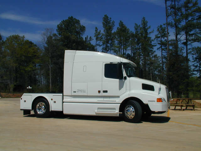
   The
white Volvo 770 in the picture to the left is owned by Richard and Dianna Lafferty. The body was built by Larry Herrin. Their cabinet is not full width because of the vertical exhaust
stack; the cabinet is "balanced" by not extending to the fairing on
the driver's side. The cabinet is 83" high,
58" wide and 19" deep and has 4 fixed shelves. There are more
pictures of this tractor in the Other Trucks album. The
white Volvo 770 in the picture to the left is owned by Richard and Dianna Lafferty. The body was built by Larry Herrin. Their cabinet is not full width because of the vertical exhaust
stack; the cabinet is "balanced" by not extending to the fairing on
the driver's side. The cabinet is 83" high,
58" wide and 19" deep and has 4 fixed shelves. There are more
pictures of this tractor in the Other Trucks album.
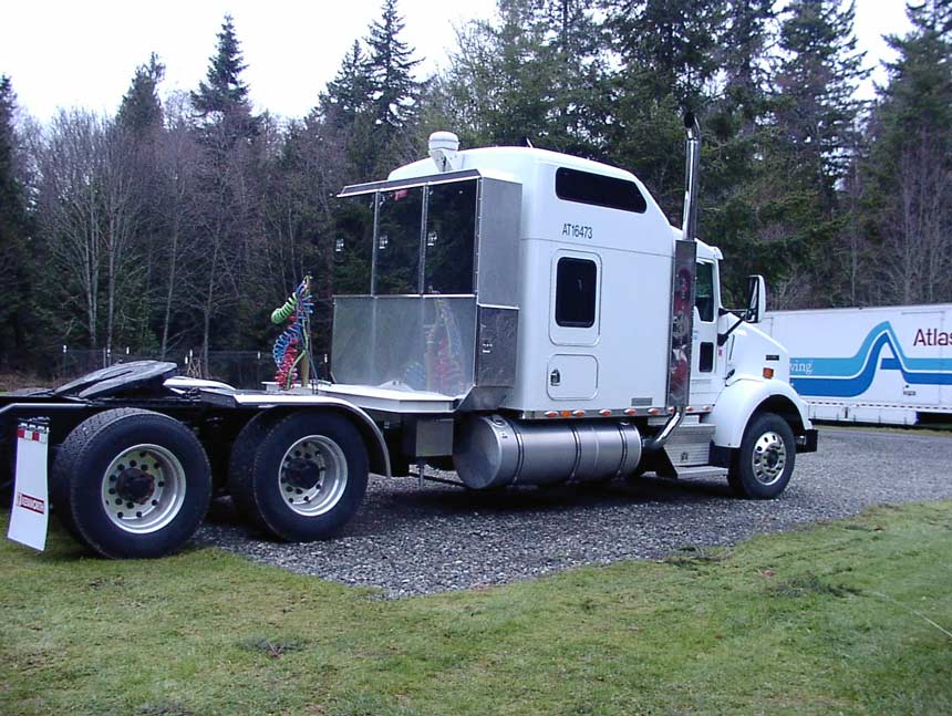
The next picture is Jeffery Roddick's T-800 with a custom drom cabinet on it. This was a working tractor, not an RV hauler, when the picture was taken - it is now an RV hauler. Note the cross storage with side access, as well as rear access to top cabinets. This drom box is 18" deep. The last picture is "Red Rover", owned by Mark and Dale Bruss. It has a standard aftermarket headache rack mounted behind the vertical air foils for stack clearance. Mark added stop/turn lights and backup lights to the cabinet. You can see more pictures of Red Rover on Mark's website http://www.dmbruss.com. Our objective was to design the smallest truck (and bed) that we could and still carry a motorcycle. We used a relatively crude Excel worksheet to help us with the design layout and to test various scenarios. You can download this worksheet for your own use (it is in an older version of Excel so more people can use it - ignore the errors generated on newer Excel versions). It contains our 182" wb tractor, Joe Johnson's 202" wb, and a layout for a T2000 and Volvo 770 with the same body on it that we have on our Volvo. It also has a 770/780/730 layout with a smart deck. Since originally publishing this, I added a "body calculator" that allows you to play with various wheelbases and see the effect on the overall truck size. Note: this file is about 200KB Truck body calculator and bed layout
In the pictures below, our truck is the white one. Mike McFall's
maroon 770 has a bed modeled after ours. There are minor differences
- the biggest difference is he added two additional "drop-in" boxes
between the frame rails. I had thought of using this space, but
because I intended to carry a motorcycle I thought it would be
mostly inaccessible, which caused me to drop the idea. In retrospect
I should have added them. They could have been used for long-term
storage. Mike's hitch is dropped down between the frame rails, which
you can see if you look at the pics carefully. Mike's maroon truck
has a simple ledge around the back of the deck - ours is "clean"
under the tailights.
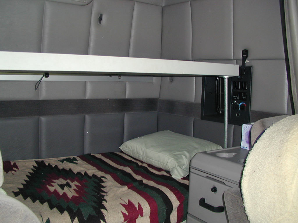
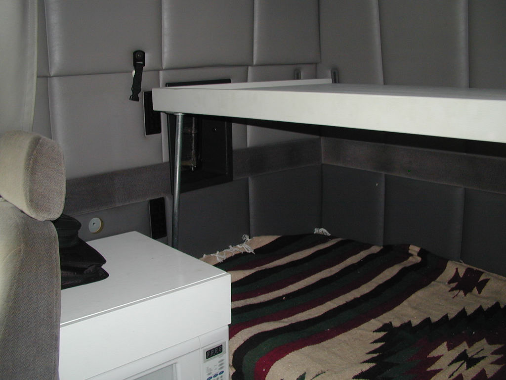
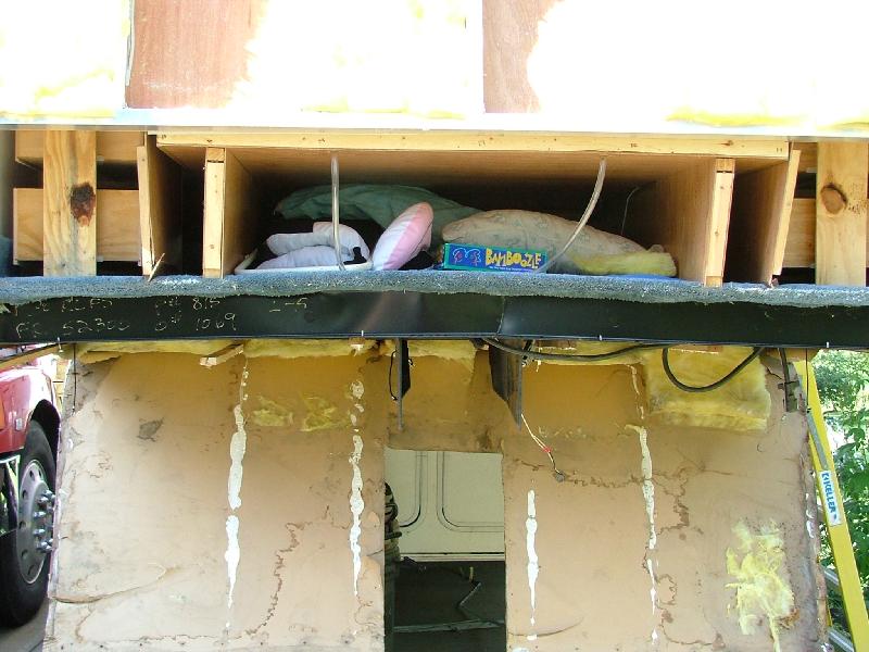
All Volvo's have the connection points for the upper bunk, and you can order that bunk from the dealer, if you can not find a surplus bunk. But they cost in excess of $800 by the time you buy the complete setup. The upper bunk in the Volvo 610, 660 and 770 are the same, and the mounting hardware is the same. (The 770 cab is wider, but the bunk is the same.) Because we overnight in our truck from time to time we wanted the extra sleeping space, but did not want to pay for an OEM bunk. We also wanted to configure the bunk so that it could be used for a backrest when in the down position. The normal bunk folds up - we wanted our bunk to fold down to the backrest position. So we decided to build our own.
The platform is made out of wood. I originally wanted to weld it up out of 1" aluminum tubing. But I changed my mind based on the expense and trouble. Instead, I ripped 2x2" stock out of 2x4's. I built a "ladder" framework from the 2x2's - everything is air nailed and glued together. I doubled the 2x2's at the front and the back for extra rigidity. This turned out not to be necessary, but without them I thought the ladder framework was a little "floppy" before being sandwiched. I then sandwiched the ladder between two sheets of 1/4" floor underlayment - again, glued and shot with trim nails. I trimmed the front and sides in scrap 1x3" oak and painted the entire thing "Volvo gray". Total cost was under $20 - the only thing I had to buy was two sheets of underlayment. The rest was scrap material. The outside dimensions of the platform are 72 1/2" x 32 1/2". This leaves about an inch clearance to the walls on the sides, which makes it easier to raise and lower the bunk into the backrest position. 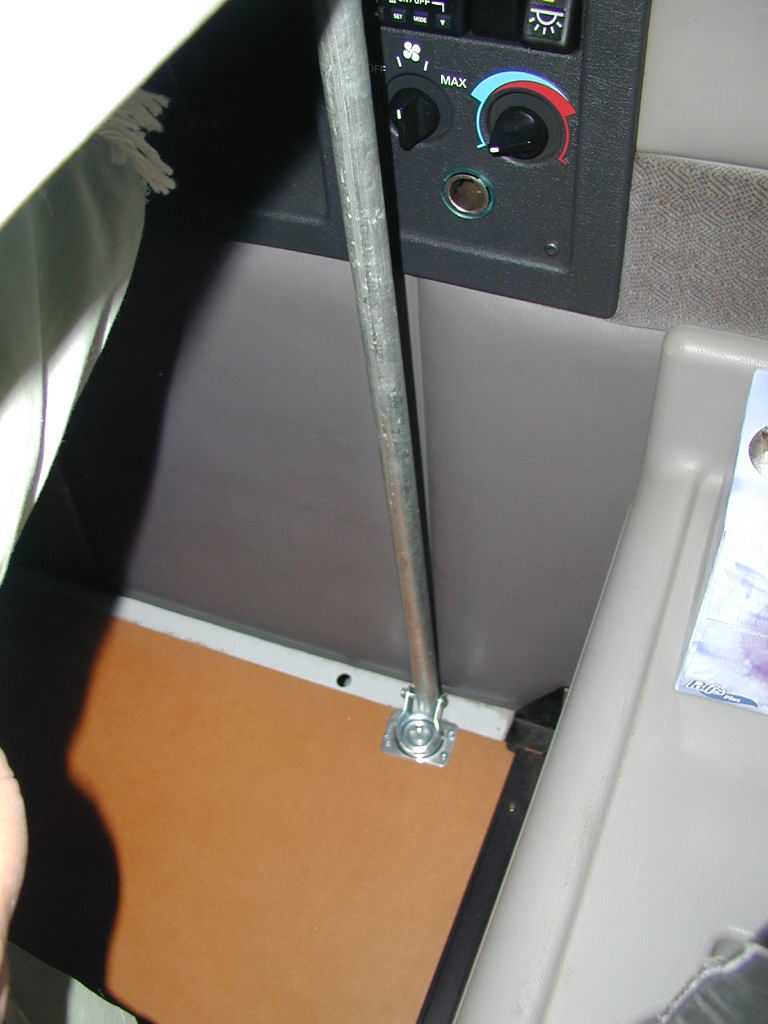 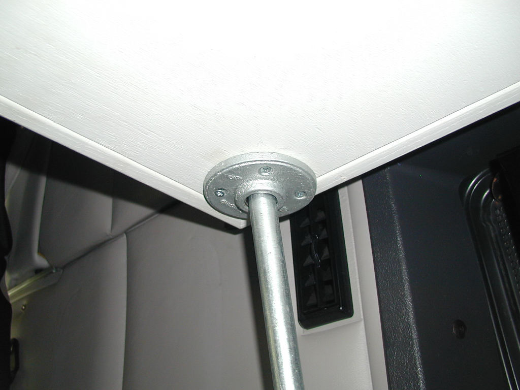 Supporting the front of the bunk is a little tricky, since I
wanted something that stores out of site, is strong, and is easy to put
into position by one person. I used 1/2" galvanized plumbing pipe for my
supports. The tops of the pipes insert into 3/4" galvanized pipe flanges
secured underneath the platform at the corners. The tricky part is how
to secure the pipes at the base in such a manner as to allow them to
swivel for both easy placement into the flanges, and to fold down
alongside the lower mattress. I used swivel casters (100 lb rating) with
the wheels removed and the pipes inserted in them. This works well - it
allows you to get the angle you need to orient the pipe properly when
the bunk is erected, and allows you to easily swivel the pipes out of
the way for storage. The casters are screwed to the plywood lift-deck
that supports the bottom mattress. Depending on your bunk setup you may
have to extend one side an inch to properly support the caster. Because
the top platform is not as wide as the bottom mattress the pipe supports
will angle in some when in the raised position. This is easily
accomplished with the swivel casters. Supporting the front of the bunk is a little tricky, since I
wanted something that stores out of site, is strong, and is easy to put
into position by one person. I used 1/2" galvanized plumbing pipe for my
supports. The tops of the pipes insert into 3/4" galvanized pipe flanges
secured underneath the platform at the corners. The tricky part is how
to secure the pipes at the base in such a manner as to allow them to
swivel for both easy placement into the flanges, and to fold down
alongside the lower mattress. I used swivel casters (100 lb rating) with
the wheels removed and the pipes inserted in them. This works well - it
allows you to get the angle you need to orient the pipe properly when
the bunk is erected, and allows you to easily swivel the pipes out of
the way for storage. The casters are screwed to the plywood lift-deck
that supports the bottom mattress. Depending on your bunk setup you may
have to extend one side an inch to properly support the caster. Because
the top platform is not as wide as the bottom mattress the pipe supports
will angle in some when in the raised position. This is easily
accomplished with the swivel casters.
The mattress is 4" foam. I wanted high density foam, but couldn't find it so we used regular foam. Four inches is thick enough - 6" would be too thick and would interfere with seating when the bunk is in the down position. The foam is comfortable, but high density would be an improvement if you can get it. Our foam is 71" x 30". We currently have it covered with a mattress cover until we can make a nicer cover from material of some sort. The bunk worked out well. If I was to do it over again I'm not sure I would change much. The platform is way overbuilt and as a consequence is heavier than I would like it. You could cut the framing by half and still have a very strong platform. I'd like to use high density foam, but if it proves to be a problem I can always add some memory foam, or switch it out. Overall cost was around $99:
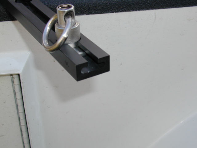
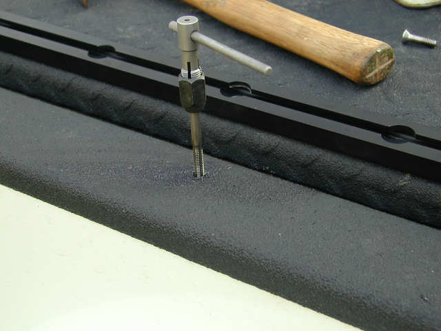
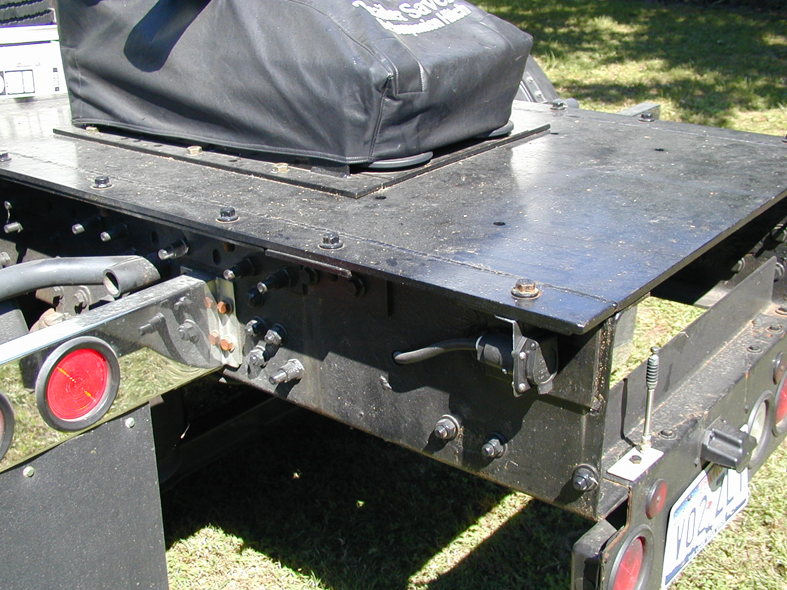
Slide-N-Lock Cargo Tie Down System I wanted a tie-down system for carrying cargo on the deck of the tractor, but I did not like the looks or utility of the traditional D rings. I used the Slide-N-lock tie down system, which I bought at Arizona Trucks. I paid $123.95, including shipping. 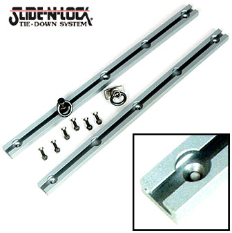 Slide-N-Lock's unique system allows you to position tie-downs right where you need them in seconds. Just pull the spring-loaded locking pin to slide the tie point smoothly and easily to the specific locating hole you want, attach your cargo and go. The Slide-N-Lock rails are made of high grade, T-6 Anodized Aluminum, and all locking pins and hardware are Stainless Steel for years of rust-free service. The capacity is 1,000lbs. per tie point in any direction. The rails come as a set, and are available in 7", 22", 68", and 93". I used the 68" set, which come with 4 tie rings. I wanted an additional 2 rings, and discovered it was cheaper to order the 7" set of rails, which come with 2 rings, than to order the rings separately. The rails come as either natural aluminum (silver) or powder coated black. The rails mount via 1/4-20 stainless bolts every 10". In my application I had to tap the frame rail of the truck body where I mounted them - since there was no access to the back of the bolts. I used black silicon caulk around the holes and on the bolt threads to keep water out of the bed rail (which is square tubing).
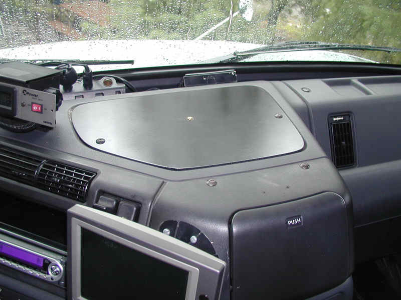
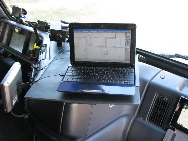
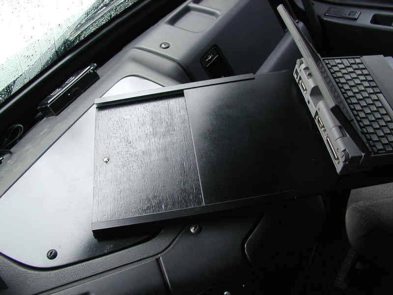
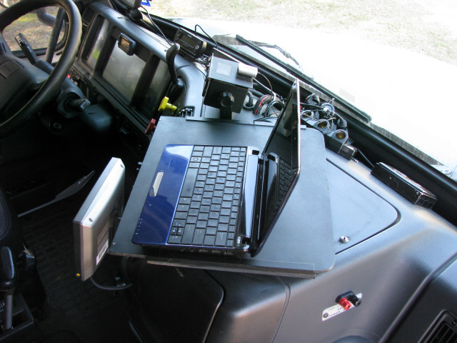
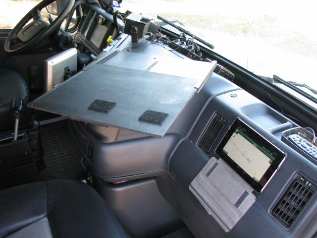
We use
a GPS in combination with our laptop for navigation. We find we only use
this when on long trips, or going into territory we have not been
before, so generally the computer is not set up on the dash. But we
needed a convenient way to view and secure the computer when it is in
use. We looked at what others had done and came up with our solution. It
works well for us, is simple to build, and gets rid of the CB holder
(over the fuse cover) which we no longer needed, since we use a Cobra
handheld CB (all functions are integrated in the CB "mike"). When the
computer is not in use, it is easy to remove the slide portion, leaving
just the fuse cover in place. click on the images for a larger view
Tablet Computer
In the picture above you
can see a tablet computer on the dash in front of the passenger seat.
This is held securely in place with Velcro. Nothing else is needed. This
tablet is a Nexus 7 - with a 7" display. It is used to run Google Maps
to supplement the navigation with Street Atlas on the Netbook. The
combination is about perfect for naviagion. We also have Co Pilot on the
tablet, if required. The tablet connects to the Internet via our private
network, powered by an aircard. It can also run off my phone if the
network goes down. It does require Internet connectivity for navigation,
but this has not proven to be much of an issue. There is an in-built
GPS. The tablet is powered via a 12-volt adaptor. In my opinion, a big negative of everyday use of our Volvo 610 (or any sleeper) is restricted rear vision - especially in parking lots. Yes, you get used to using the mirrors and getting out and looking, etc. But stuff that is close is still in danger, no matter how careful you are. I find having a rear vision system convenient. As of August 2005 we have three cameras on our tractor. One on the back of the cab, one on the right mirror bar, and one directly behind the hitch.
Note: as of 2013 the best value for the $ that I can find on cameras and backup systems is on Ebay. Products sold by the seller 'leviathan_holdings' are high quality and work well. I have many, as do many other people, and we have had good luck with them.
I wanted a cheap system, but still effective. This meant assembling the pieces myself. The pre-packaged systems are great, but run upwards of $800 (as of 2010 you can find nice systems on Ebay for as little as $250). After researching it, I decided to buy a good monitor and a cheap camera. I thought this would suffice for my needs and it has turned out OK. I used an X10 Anaconda color wired camera as the primary camera on the back of the cab. Using a wireless camera is iffy, according to the people that have tried it - some work out - some don't. And since you have to supply 12-volt power to the camera you are running wires anyway. This X10 camera has 60-degree field of view. This is the minimum you need. I can see three lanes behind the tractor - one on each side of my lane. More field of view would be better, but this camera only cost $49 - which met my price goal. The image quality is acceptable for rear viewing of cars and other stuff, but marginal for hooking up. The issue is partly a function of the size of the monitor, in combination with the size of the lens on the camera, and the distance of the camera from the hitch - the hitch is a pretty small object as it appears on the monitor. I put white alignment stripes on my hitch plate and hitch head and this allows me to get real close to perfect alignment. A better quality camera would improve hookup tremendously, as would mounting the camera lower on the truck cab. The disadvantage of mounting the camera lower (say on the lowest grab bar) is that it is more difficult to route the wires invisibly. Everything is a tradeoff. The position I chose gives me good rear vision but is not optimal for hookup, but we pretty much do the hookup without the camera anyway.
To make hookup super-simple you could mount the camera on a stalk right behind the hitch. Several people who hookup without assistance have done this, and it works well. This does minimize your rear view, though. To solve this "quandary" we installed a third camera dedicated to hooking up. It is directly behind the hitch plate itself. This camera is a "Sam's Club" $39 color camera with IR capability. The image quality is about the same as the X-10's, as is the field of view. The real difference is that the Sam's camera is not weather resistant, so you have to build some sort of enclosure to protect it. I used PVC pipe.
My primary camera is mounted below the rear (little) window, resting on the horizontal rain gutter. The wire is run within the gutter, and down the gutter line along the vertical airfoil, then under the truck. It is not very noticeable, being nestled into the gutter line of the vertical foil, but you might want to paint the wire the color of your truck. The camera and wire is held onto the truck with white adhesive door/window caulk (good thing we have a white truck - if you have a colored truck, you might want to consider black caulk). It holds it fine. The camera comes with 60' of wire - more than enough. Everything (power/data) runs through one wire set, so hookup is simple. Check the X10 site for details - X10.
This camera is intended for use with home automation and security systems, so it uses 120-volt power reduced to 12 volts by an integral power brick. Just cut the brick off and wire the camera directly to an ignition-switched 12-volt power source in your fuse block. The camera uses minimal power, so don't worry about overloading whichever circuit you tap. I just found an unused fuse block that was ignition-switched and plugged in there. Make sure you maintain polarity - the white-striped wire is the positive feed. My ground is supplied from the back of the CB Radio power supply. The X10 wire code and pinouts is in a diagram at the bottom of this page. After using the camera for a year, I added a sun hood to it (the white cover in the picture, below). The camera would occasionally blank out, due to direct sun on the LCD. I used some PVC pipe and cut it to an appropriate size. It is held on with adhesive caulk.
The Monitor
Total cost was - $49 camera, $196 for monitor (off of Ebay, including shipping/insurance). There were no extra costs, since the stand that came with the monitor was sufficient.
Future Additions
There is a blind region around 4-o'clock on the truck, because there are no windows on the passenger side of the sleeper. This makes it exciting to pull out of any intersection that Y's to your right. I do not have a powered passenger mirror, which would help minimize this problem. Because the monitor supports two video feeds I'm thinking about mounting a second camera on the passenger-side vertical foil angled out to the right of the truck. This would help with blind-side back-in campsites as well. Adding the second camera for $49 is a lot cheaper, and probably a superior solution, to adding a powered right mirror.
Update: after almost 2 years of living with limited vision to the dead area at 4 o'clock I installed a second camera. Joe Johnson gave me a "spare" X10 B&W camera (thanks Joe) and I mounted it on the mirror arm with "tacky-tack" (used to mount things in the RV). I'm a little concerned with impact from closing the door affecting the camera over the long-term. We will have to wait and see (update: the tacky-tack has held the camera in place for over 7 years with no issues). It works great when you need it, especially for blind-side backing - no more guessing where you are when backing the trailer into those "backwards" campsites! Of course, if you have a powered mirror you can pretty much circumvent this problem that way.
I will probably paint the camera on the back of the cab white at some time - it will blend with the truck better this way.
After six years glare on the monitor has not been a problem, but shrouds are available that will help keep glare from the screen, or you can easily make your own. If this proves useful, I may add a shroud in the future. Positioning the monitor up on the dash would make it more subject to glare, and I think a shroud would be necessary.
Update 2013: after almost 10 years this camera is pretty worn out - UV has degraded the lens cover enough that it is affecting the picture quality. Time for a replacement.
Managing Multiple Cameras
If you have a monitor that supports multiple video inputs then managing multiple cameras is not a problem, unless you want to have more than two cameras - the typical number of video sources monitors support. Since we now have three cameras I thought I would put in a switched system to feed the monitor, and circumvent the selector in the monitor itself.
If you use X10 cameras, they only power up when they are "selected" by the base module. They take a little time to warm up, so ideally you want them all powered up and ready to use. The easiest way to do this is with a "selector box", which you will build yourself.
In order to do this you need to know the pin-outs on the cameras RJ-45 connector. The X-10 pinouts, left-to-right, as viewed from the end of the connector, with the tab on top is: 1 - ground, 2- video (yellow wire), 3 - ground, 4 - 12 volt (red wire), 5 - ground, 6 - audio (white wire) - see the diagram at the end of this page.
I built my selector box from a medium size plastic project box obtainable at Radio Shack. I used a 6-position rotary switch, also from Radio Shack. This switch requires you to solder the feed lines on, but it is a fairly simple process. To feed the camera outputs from the back of the truck to the dash I used category 5e Ethernet cable with connectors already on - 25' was more than enough. I ran this from the truck electrical panel mounted in the drivers compartment to the dash. Camera power is supplied by an ignition signal sent down the cat 5 cable on one of the lines from the fuse box at the dash to a relay. The relay controls power to the camera bank at the rear. The relay is used to simplify the wiring run from the cab - everything goes across the very light gauge cat5 cable. All cameras are "hot" when the ignition is on. This allows instant switching between cameras with no warm-up time.
At the project box on the dash the cat5 cable terminates in an RJ-45 jack mounted in the box. Within the project box the various camera inputs run to the appropriate switch position. A single output from the switch feeds the monitor. This way, the switch allows you to flip between camera views, while maintaining power on all cameras. It sounds complicated, but is really quite simple. It is best if you solder the connectors onto the rotary switch.
At the driver compartment electrical center, where the rear camera inputs are centralized, I built a video jack board to plug the cameras into. The excess camera cable is tied to the frame under the truck. You could easily cut this excess cable off, and just patch the raw wire ends to the cat5 cable. I used the plug board to make changes easy. To interface to the cat5 cable I cut the plug off and used a terminal strip to terminate all the ends. The plug board is wired directly to the terminal strip. This way I can move things around easily. You certainly would not have to do this complex of termination...you could simply wire-nut the appropriate camera ends to the cat5 cable.
The stock Delco radio
that was in our Volvo was not a very good radio, and it did not have
a CD player, only a cassette player. We upgraded the radio to a
Kenwood KDC-MP6025. It has an inbuilt Sirius display/controls with
an external "brain" box (the satellite tuner). I chose Sirius over
XM because the general consensus is that you get less drop outs with
Sirius. This is because of the location of the Sirius satellites,
and the fact that there are at least 2 satellites visible in any
location vs. a single satellite with XM. The XM satellites are in
geo synchronous orbit (like the DirecTV and Dish Network
satellites). The Sirius satellites do figure 8's over the US. At
least in theory, the Sirius satellites should provide better
reception.
I looked at the external satellite radio receivers that can be moved from the truck to the trailer, or into another vehicle. I chose the integrated display (built into the radio) primarily because I have no need to move the receiver/display and I definitely don't need another box on my dash. It is getting crowded as is. The radio is an upper line radio. It has 25 watts x 4 RMS of power, which makes a remarkable difference in the listening experience. I am definitely NOT an audiophile, so my requirements are not as strict as some. But the difference between the radios is both readily apparent, and huge. I thought I would have to upgrade the stock speakers, but this radio makes such a difference I probably will not do it. I may add an amp and subwoofer later and keep the existing speaker set. You can always use the extra bass. If I did this, I would leave the front speakers powered by the radio, and move the rear speakers to the amp. Installation The Sirius satellite tuner box went in the space right behind the cup holders - vertically. There is 20 feet of cable from the radio to the satellite tuner box, so you can locate it pretty much anywhere. The limiting factor in location was the amount of antenna coax supplied with the magnetic base antenna. There was just enough antenna wire to reach from the roof to the cup holder. Since the tuner does not generate heat, it is OK to mount it here. It is easily removed for servicing, or to move it to another vehicle if I sell the Volvo. The antenna mounted on the passenger side visor brace (on an existing screw), on a piece of metal stock for horizontal magnetic mounting. It is important to maintain a horizontal position for the antenna. The tiny coax was run through the visor light trim piece towards the passenger side. I used white silicon caulk to secure it where required. It then runs downward behind the vertical windshield trim to the door hinge area where a piece of horizontal trim allows it to enter the door area without exposure. It proceeds through the rubber door trim and along the front of the dash. It is not visible. It enters the dash through the Eaton autoshift wire run, and then across to the fuse center (behind the cup holder) to the tuner box. The whole thing is neat, and took half an hour - start to finish. The radio went in just as easy. Sirius Reception Sirius reception is 100% so far - and I've been trying to beat it. There are no directional issues (truck facing certain directions) with the mounting location on the visor, and the truck roof, which rises steeply behind the visor, does not interfere with signal acquisition. The antenna is not visible from the ground. (One note on the visor mounting position - it worked well on a Volvo 610, with a mid-height roof. I'm not sure that it would work as well on a full-height truck because of the additional cab above the visor.) In areas where XM is known to lose signal (like 4th of July Pass in Idaho) I have no problems. I have also driven on densely treed two lane roads, where the trees are right up to the road edge. Again, no reception problems. Another thing I've noticed - in heavy rain there are no drop outs like with satellite TV. So I guess that the Sirius birds are helping me out. I now know why people love satellite radio, although I never thought I would. But the sound quality is NOTICEABLY better than over the air music, even to a non-audiophile like me. So, I guess I'm a happy camper. Here are the
Volvo wire id's for the speakers: We added a sink to our Volvo 610. Some 770/780's come with sinks in them, but the 600 series does not. There are various methods of adding them; the biggest issue is plumbing in the tanks and pump. The actual sink is the easy part. You can see our sink project - and some others - in our Picasa album. 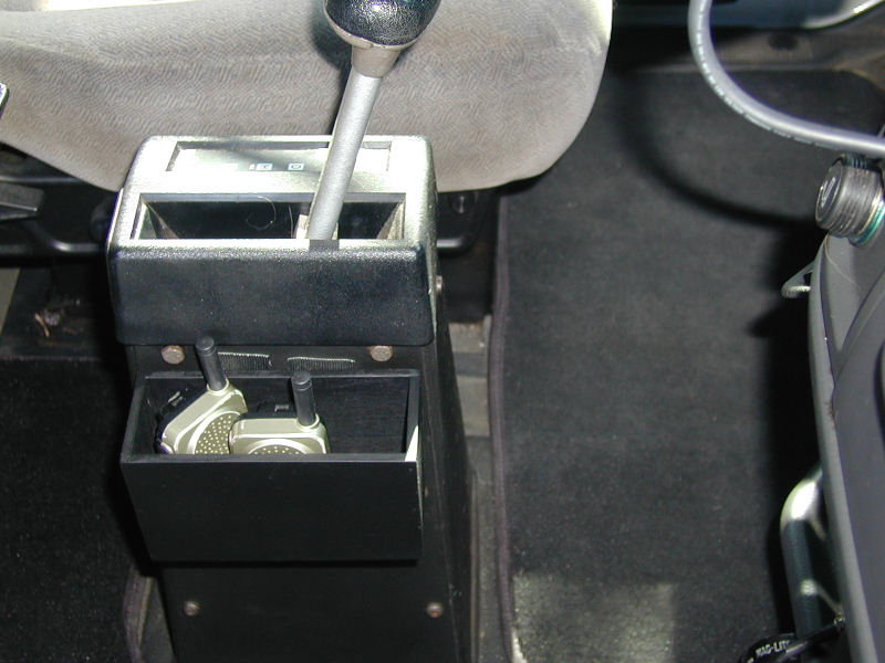 We wanted a way to keep our FRS (2-way) radios handy. We use these
all the time. We take them into Wal-Mart (that way we don't have to
stay together), into the mall, around campgrounds, and of course, we
use them when we are backing into our site (along with hand
signals. Danielle does the campground registration, so she grabs
one when she goes into the office, in case she has to ask me
something. We wanted a way to keep our FRS (2-way) radios handy. We use these
all the time. We take them into Wal-Mart (that way we don't have to
stay together), into the mall, around campgrounds, and of course, we
use them when we are backing into our site (along with hand
signals. Danielle does the campground registration, so she grabs
one when she goes into the office, in case she has to ask me
something.
We first tried to directly Velcro them to the side of the autoshift
console. That "kind of" worked, but they kept falling off, or the
Velcro kept coming off the back of the radio.
So, I built a little box to put them in. The box hangs from Velcro,
and is sized to fit on the console without interfering with walking
through. Our cell phone also fits into the box, although it is not
shown. The entire thing works well.
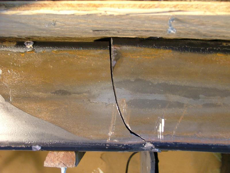
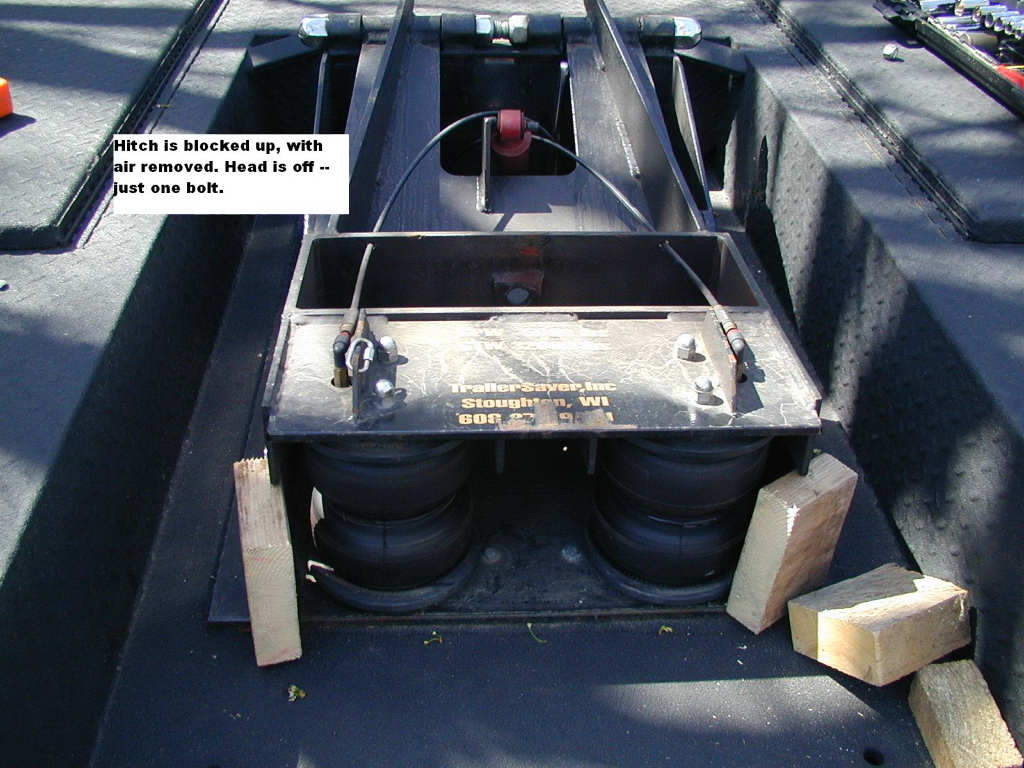
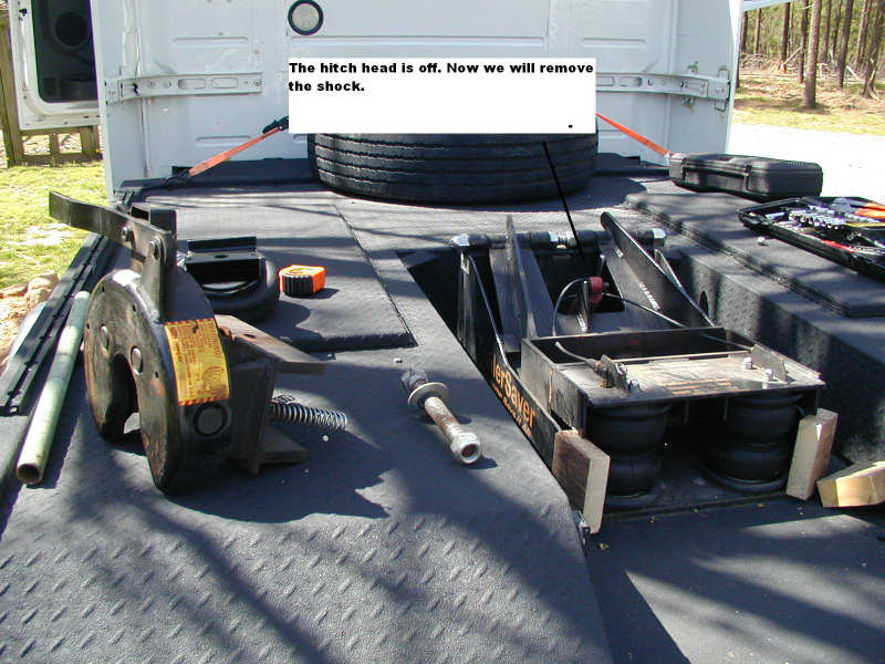
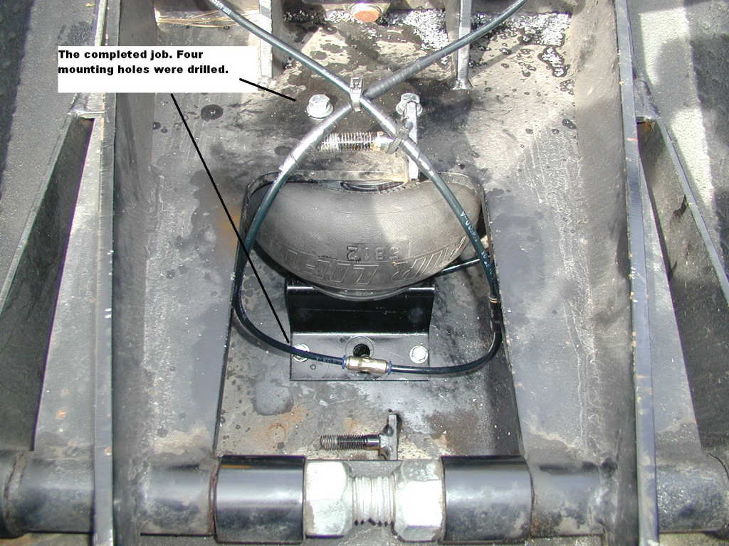
There are a number of people that tow with the commercial hitch, with no reported problems due to impact. Others who have towed with the commercial hitch have had fractured hitch heads and welds fractured on the trailer. If you do tow with the commercial hitch, you would want to be sure that you convert the tandem axles to single (lighter suspension). In the pictures above you can see the result of towing with a HDT and the commercial hitch (click on the second picture to expand it). Could it happen to you? Maybe not, but why take the chance? The hitch is not the place to save money, in our opinion.
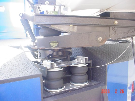
We decided to convert to an air suspension hitch based on our observations of our Reese hitch on our F550. We are glad that we did it; watching the trailer float through rough roads confirms to us that there is an advantage to having the air hitch in addition to the existing air suspension on the tractor. Whether it is worth the expense is your own judgment. Since we intended to have a hauler bed built, leaving the commercial hitch on was not a viable alternative for us.
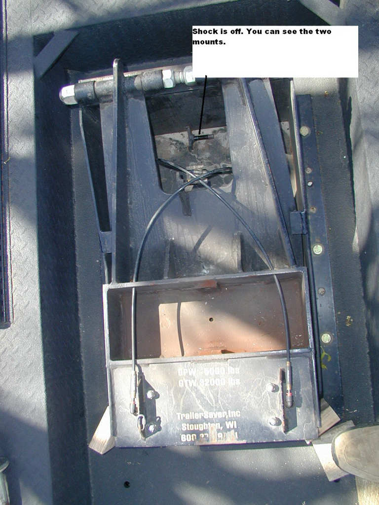
Within the class of truck mounted hitches there are many to choose from. At the time I built up the truck, the primary selection criterion for us was the hitch plate height. Many of the available hitches were too high for our trailer to ride level. These hitches are primarily designed for use with MDTs, which have a lower frame height, and thus a lower mounting height for the hitch. When applied to a class 8 tractor many of them end up being too high for the trailer to ride level. TrailerSaver has the lowest riding hitch we could find, thus our choice of TrailerSaver. Since we installed the Trailersaver hitch we have discovered the Advanced Air Hitch http://www.advancedairhitch.com/. It is also 10" high, and has a Binkley head, with air bag side cushioning, as well as fore-aft air bag cushioning. It also has a higher pin weight rating than the standard TrailerSaver. It is an interesting hitch and is worth a look if you are in the hitch market. It costs considerably more than a TrailerSaver, so we would not have used it, even if it was available at the time we chose our hitch.
If and when I build a new truck I will use what I consider the best hitch available on today's market - the ET Hitch. Nothing is built stronger, and it is designed to drop into the frame rails of the tractor. It has a steel bottom plate integrated into the design, so that saves you adding the steel plate. It is competitively priced and is simply the best hitch to use, in my opinion. A video describing the ET Sr. hitch is here.
Many people add extra weight in the form of a 1 inch steel deck that they mount the hitch on. This is a good idea if you can afford the sacrifice in final hitch head height. In our case, we decided that we could not afford the height increase. Adding the extra weight would result in a better ride when bobtail, and slightly better braking performance. However, we found the ride fine with the 600 lbs added by the steel plate and the TrailerSaver hitch, even with our short wheelbase.
While having the bed built we temporarily removed the steel plate and hitch. I did not think this would make much difference in the ride quality - boy was I wrong! It was like night and day - removing the 600 lbs RADICALLY changed the ride quality. You really do need that weight. Now that the body is on (to the tune of about 2000 lbs - with the hitch) the ride has improved even further.
Our final ride height on our first trailer we towed with the tractor (the Kountry Star), when hooked up with 75lbs. of air in the hitch, and with 3640lbs on the pin, was 20.5" from the tractors steel deck plate. The deck plate itself is 39 1/4" from the ground and it is 11" from the trailer hitch plate down to the tractor deck plate (this makes the hitch head about 50 1/4" from the ground). On that trailer, the trailer hitch head was fully retracted. Measuring the beltline of the trailer indicated a 1.5" drop from the front to the rear of the 36 foot trailer. This was not noticeable visually, and the trailer level indicated that the trailer was actually level so it was hard to tell if it was off any. Note that TrailerSaver says that the hitch plate in its lowest location is 10" (from the mounting deck) but this is without the required air in the hitch, which added the extra inch. We were probably running a little more air than we need in the hitch - we could have gone down to 65 lbs or so and stayed within the guidelines of the hitch, but this does not lower the final height significantly.
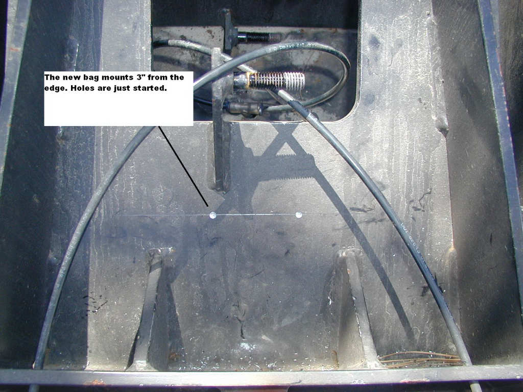
Our next trailer, a Royals International, was lifted 3" by the previous owner, so there were no level issues. We did have to recess the trailer hitch head to it's next-to-last position in order to get level. With the trailer pin weight slightly over 5,000 pounds we had to run about 95 psi in the hitch - which is too high for optimal cushioning. You can add a third air bag to the hitch, which results in the ability to run reduced pressures - resulting in a softer ride for the trailer. After about a year, we added this third air bag - mainly to increase the current 5000lb. pin weight rating (which we are at) to 7500 lbs.
When looking at hitches, measure carefully. Ride height is the single most critical measurement. You do have the option of dropping the hitch into the frame rails, but this will add cost. Also, be aware that if you do this, your rear air suspension dump may be limited by the amount you recess the hitch unless you relocate some of the air system components. You might also have to remove, or modify the cross-frame brace on a Volvo 610 - depending on where you locate the hitch. Assuming you bolt in a flat plate for the hitch, it probably would not matter if you remove the cross brace. If you drop the hitch between the rails, a good final hitch height to aim for is 46-47". This would accommodate almost all trailers, without raising them. If you want to see an example of a hitch mounted between the frame rails, look at Mark and Dale Bruss's website: http://www.dmbruss.com. They have quite a bit of good info on converting their Volvo 770.
When we build the next truck body we will drop the hitch between the rails, even though it will complicate things on the build. On Volvo's there is a cross member between the frame rails to the rear of (or near) the axle. There are a lot of air-system valves and components mounted on this cross-brace. Depending on where this is, and where you want your hitch location, you may need to cut this down or remove it. Some people move it more forward in order to have room for the hitch plate to drop between the frame rails. On a short wheelbase conversion like ours there is no room to move this brace forward without interfering with the ride level valve and other components. So on a short wb tractor where you want to recess the hitch, your only practical choice is to move the hitch far enough to the rear to avoid interfering with the cross-brace. Careful planning of the body is required to get this right. There is no problem moving the hitch 3-4' behind the axle center line.
If you are concerned about twisting forces flexing the frame then you might add a cross brace at the top of the frame members. The hitch plate will brace the bottom frame members. All frame shops I have discussed this modification with have approved this. Especially if you have a body on the truck there will be more than enough bracing provided.
Adding the Third Airbag
Because our pin weight on the Royals International ran slightly
over 5000 lbs (depending on what was in the trailer and where)
we decided it would be wise to add the optional 3rd air bag to
the TrailerSaver hitch. This bag costs $300 - you can install it
yourself. With the bag comes 2 bolts for the top mount, 2 self
tapping screws for the bottom mount, a T for the airline, and
about 12" of extra airline for the new bag. TrailerSaver says it
takes about an hour to install. Maybe after you've done a few,
but I would plan on 2 hours.
Installation instructions are on the TrailerSaver website. There
are a couple of things to watch out for that they don't tell you
about. First, check the air fitting that is already in the
bottom of the third bag. You need to make sure it is tight, or
you will be removing the bag later to fix the air leak (wonder
how I know this?). Second, make sure you do not over tighten the
2 bolts in the top of the airbag, where they go through the
swing arm. The holes tapped in the airbag top plate are very
soft and can be stripped.
The entire thing is really pretty simple to do. The hardest part
is drilling the 4 holes. You may only have to drill 2 holes,
since newer hitches already have the swing arm holes drilled
(for mounting the top of the airbag).
The pictures below tell the story.....click on them to expand.
|
|||||||||||||||||||||||||||||||||||||||||||||||||||||||||||||||||||||||||||||||||||||||||||||||||||||||||||||||||||||||||||||||||||||||||||||
|
|
||||||||||||||||||||||||||||||||||||||||||||||||||||||||||||||||||||||||||||||||||||||||||||||||||||||||||||||||||||||||||||||||||||||||||||||
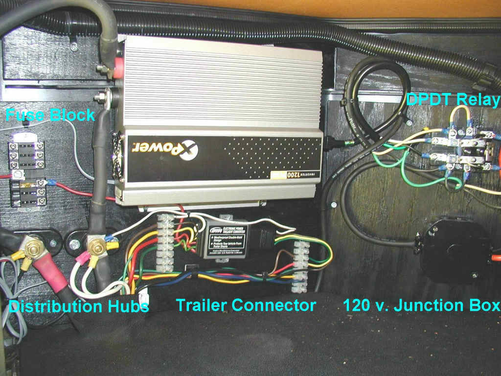
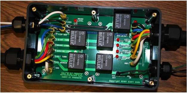 At
the time I modified my truck I used a Hoppy Model 46255 converter to supply the appropriate
signals. This is a powered converter - the advantage is that it isolates
the truck electrical system from the trailer, preventing any shorts in
the trailer from impacting the truck. There have been enough issues with
the 46255 that I would no longer use it. IF I was going to use a Hoppy, I would only use the Hoppy
46365, which can handle 8 amps. The Hoppy converter is the gray box
directly below the inverter in the picture of the truck wiring center at
the top of this section. Look in the Resource Listing section for
sources for the Hoppy.
At
the time I modified my truck I used a Hoppy Model 46255 converter to supply the appropriate
signals. This is a powered converter - the advantage is that it isolates
the truck electrical system from the trailer, preventing any shorts in
the trailer from impacting the truck. There have been enough issues with
the 46255 that I would no longer use it. IF I was going to use a Hoppy, I would only use the Hoppy
46365, which can handle 8 amps. The Hoppy converter is the gray box
directly below the inverter in the picture of the truck wiring center at
the top of this section. Look in the Resource Listing section for
sources for the Hoppy.
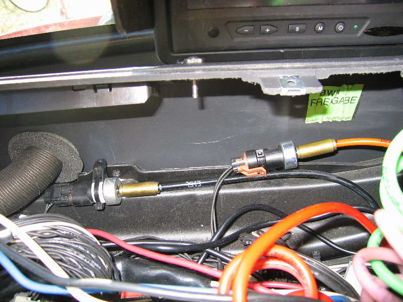
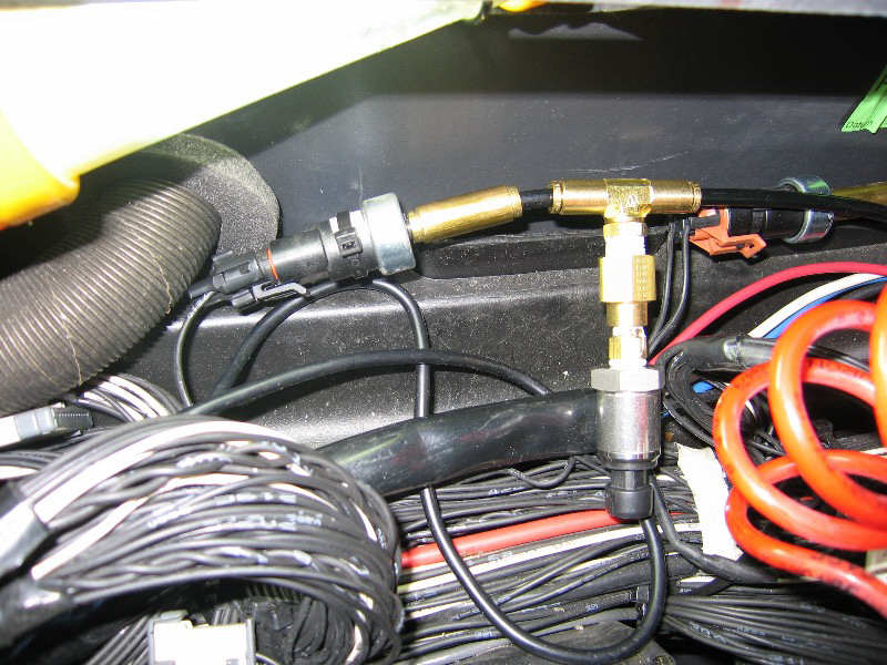

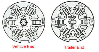 To
the left are the wire locations of the RV 7-way connector. You must go
by position of the wire relative to the notch - not just by color, since
there is no standard for the colors of wires. The general layout is as
follows:
To
the left are the wire locations of the RV 7-way connector. You must go
by position of the wire relative to the notch - not just by color, since
there is no standard for the colors of wires. The general layout is as
follows: